



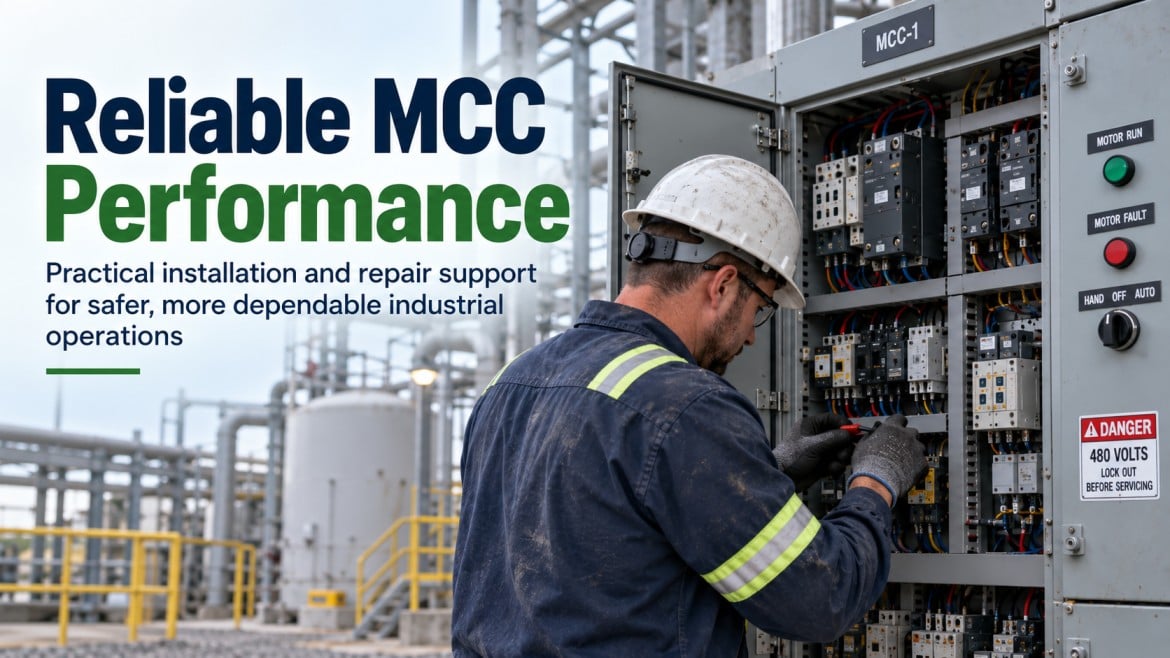
MCC installation and repair involves positioning and anchoring MCC sections, connecting bus and wiring, verifying protective device ratings against available fault current, and testing before energization. Repair addresses individual starters, breakers, or wiring; replacement is considered when the enclosure, bus, or obsolete components can no longer support the facility’s motor loads safely or reliably. Qualified electrical personnel should evaluate site-specific conditions before work begins.
Key Takeaways
- An MCC’s protective devices and bus must be rated for the facility’s available fault current, not just its connected motor loads; this requires a fault-current study, not an assumption.
- Repair can be the more practical option when failures are isolated to a specific bucket, starter, or wiring segment and the enclosure and bus remain structurally sound; replacement becomes more likely when obsolescence, corrosion, or repeated failures affect multiple sections.
- Work inside an operating facility requires coordination around production schedules, and planned shutdowns should be scoped early since they affect safety planning, sequencing, and cost.
- Louisiana’s humidity, heat, and coastal-adjacent air quality affect enclosure selection and long-term reliability, so NEMA rating and installation environment should be assessed together, not treated as an afterthought.
- Testing and commissioning insulation resistance, grounding continuity, phase rotation, and protective device verification should be completed and documented before an MCC is energized, not treated as optional.
A motor control center failure, or an outdated MCC that can no longer support a facility’s motor loads, creates a direct operational risk: it can stop production, trip protective devices unpredictably, or expose personnel to electrical hazards. Facilities considering Motor Control Center installation, repair, or replacement in Louisiana need to weigh several site-specific factors together: available fault current, code requirements, existing wiring condition, environmental exposure, and how the work will be sequenced around ongoing operations. This article covers what an MCC does, when repair versus replacement makes sense, what the installation and testing process involves, and what affects project cost and timeline.
What Is a Motor Control Center?
What an MCC Does
An MCC is an assembly of one or more enclosed sections housing combination motor starter units, each combining a disconnect, overload protection, and a contactor or breaker that receive power from a common bus and distribute it to individual motor circuits. Rather than wiring each motor back to a separate disconnect and starter scattered around a facility, an MCC consolidates motor control and protection into a single, centrally located assembly. This makes motor circuits easier to operate, maintain, and troubleshoot, since starters, breakers, and related control wiring are grouped in one location instead of spread across a plant.
Main Components and Configurations
A typical MCC includes a horizontal main bus fed from the facility’s electrical distribution system, vertical buses that feed each section, and individual plug-in or bolt-on units (commonly called buckets) containing a starter, overload relay, and disconnect or breaker for each motor. Units may also include VFDs, soft starters, or specialty control devices depending on the application. MCCs are available in low-voltage and medium-voltage configurations, and sections can typically be added over time provided the main bus and incoming service have enough spare capacity, a detail worth confirming before assuming an existing MCC can simply be extended.
Common Industrial Applications
MCCs are used wherever a facility operates multiple motors that need centralized control and protection, pumps and blowers in water and wastewater systems, conveyors and mixers in manufacturing and processing plants, and compressors and cooling equipment in industrial and energy facilities, among other motor-driven equipment across process industries. The specific starter types, protection settings, and control integration should reflect the actual equipment an MCC serves rather than a generic configuration.
When a Facility Needs MCC Installation, Repair, or Replacement
Adding Motors or Expanding Production
When a facility adds equipment, a new pump, conveyor line, or process area, the motors driving that equipment need control and protection that the existing MCC may or may not have capacity for. Before assuming new sections can be added, it’s worth verifying that the existing bus rating, available spaces, and incoming service capacity can support the added load. Expanding an MCC without checking these factors can result in an assembly that is undersized for the facility’s actual demand.
Replacing an Outdated or Undersized MCC
Facilities running older MCCs sometimes face a different problem: the assembly still functions, but starter types, breaker ratings, or the bus itself no longer reflect the facility’s current motor loads or available fault current. Obsolete components can also become difficult to source, extending downtime when something does fail. Replacement becomes a more serious consideration when these issues affect multiple sections rather than one isolated component.
Repairing Failed or Damaged Components
Not every MCC problem requires full replacement. A tripped breaker, a failed overload relay, damaged wiring in a single bucket, or a starter that has reached end of life can often be repaired or replaced at the component level, leaving the rest of the assembly in service. The right approach depends on what actually failed, why it failed, and whether the surrounding bus, enclosure, and wiring show signs of broader deterioration.
When Repair Makes More Sense Than Replacement
Repair tends to make more sense when the failure is isolated, the enclosure and bus are structurally sound, replacement parts are available, and the facility’s load requirements haven’t outgrown the MCC’s rated capacity. Replacement becomes more appropriate when failures recur across multiple sections, when available fault current exceeds what the existing equipment is rated to withstand, or when parts for obsolete equipment are no longer supportable. This is a facility-specific determination that should follow an inspection of the actual equipment rather than a general rule of thumb based on age.
MCC Installation Requirements and Code Compliance
Reviewing Motor Loads, Voltage, and Bus Ratings
Before installation begins, the motor loads an MCC will serve need to be reviewed against the proposed bus rating, voltage, and available spaces, so the assembly is sized for the facility’s actual demand rather than only its current one. This includes confirming full-load and locked-rotor current for each motor, feeder conductor sizing, and how much spare capacity the facility wants to retain for future additions.
Available Fault Current and Short-Circuit Ratings
Every MCC and its protective devices carry a short-circuit current rating (SCCR) that must equal or exceed the available fault current at the point of installation. This value comes from a fault current study specific to the facility’s electrical distribution system; it is not something that can be estimated from nameplate data alone. Installing an MCC with an SCCR below the available fault current creates a serious safety hazard, since protective devices may not be able to safely interrupt a fault.
NEC and Louisiana Electrical Code Requirements
Louisiana enforces the National Electrical Code as adopted and amended by the Louisiana State Uniform Construction Code Council, which adopted the 2020 edition of the NEC, effective January 1, 2023, as the statewide minimum electrical code. NEC requirements relevant to MCC installations include working clearances around electrical equipment, disconnecting means, overcurrent protection, and grounding and bonding provisions. A full review of applicable code sections for a specific project is a matter for licensed electrical personnel and the local authority having jurisdiction; this article summarizes general requirements rather than certifying compliance for any particular installation.
Permits, Inspections, and Working Clearances
MCC installation and major repair work typically requires an electrical permit and inspection by the local authority having jurisdiction, in addition to meeting NEC working-space clearances in front of and around the equipment. Clearance requirements depend on voltage and equipment exposure classification, and they affect where an MCC can physically be located within a room. These requirements should be confirmed with the local jurisdiction before installation planning finalizes equipment placement.
Planning for Future Expansion
If a facility anticipates adding motors or processes within the next several years, it’s worth specifying spare bus capacity, extra vertical sections, or larger incoming service during the original installation. Retrofitting capacity into an MCC after the fact is typically more disruptive and expensive than building it in from the start.
Preparing for MCC Installation
Reviewing One-Line Diagrams, Floor Plans, and Elevation Drawings
Installation planning starts with reviewing the facility’s one-line diagram, floor plans, and elevation drawings to confirm how the MCC will tie into the existing electrical distribution system, where it will physically sit, and what clearances and access routes are available. Discrepancies between drawings and actual field conditions are common in older facilities and should be identified before equipment arrives.
Preparing the Foundation and Installation Area
MCCs require a level, properly prepared foundation or floor stand sized to the equipment’s footprint and weight, with attention to any required sill channel or housekeeping pad. The installation area also needs adequate clearance for the equipment itself, working space required by code, and access for future maintenance.
Planning Conduit, Cable, and Busway Entry Points
Conduit and cable entry points, whether top, bottom, or rear entry, need to be planned around the MCC’s design and the facility’s existing raceway system. Getting this wrong after the equipment is set in place can mean cutting into a finished enclosure or rerouting conduit, so entry point planning belongs early in the process.
Receiving, Inspecting, Handling, and Storing MCC Equipment
MCC sections are heavy, and shipping damage or moisture exposure during storage can affect insulation and internal components before the equipment is ever energized. Sections should be inspected against the packing list and for shipping damage on arrival, and stored in a dry, temperature-stable area if installation won’t happen immediately.
The MCC Installation Process
Positioning, Leveling, and Anchoring Sections
Each MCC section is positioned according to the approved layout, leveled, and anchored to the foundation or floor stand. Proper leveling matters for both structural stability and for the alignment of the bus connections between sections.
Joining Shipping Sections and Connecting Bus Systems
Where an MCC ships in multiple sections, the horizontal bus is joined between sections and torqued to the manufacturer’s specifications, with attention to proper bus alignment and insulation barriers. Improperly torqued or misaligned bus connections are a common source of later overheating and failure, which is why this step follows manufacturer documentation closely rather than field judgment alone.
Installing Conduit and Routing Power, Control, and Communication Wiring
Power, control, and any communication wiring (for VFDs, monitoring, or SCADA integration) is routed according to the planned entry points, with separation maintained between power and low-voltage control or signal wiring to reduce electrical noise and interference.
Terminating Connections, Grounding, and Bonding
All power and control conductors are terminated and torqued to specification, and the MCC’s equipment grounding conductor is bonded to the facility’s grounding system per NEC requirements. Grounding and bonding aren’t just a code checkbox; they’re what allows protective devices to clear a fault safely and what limits touch-voltage hazards if equipment becomes energized unintentionally.
MCC Starters, Drives, and Protection Components
Motor Starters and Overload Protection
Combination starter units pair a contactor with overload protection sized to the specific motor’s full-load current, so the starter interrupts power if the motor draws sustained excess current. Overload settings need to match actual motor nameplate data; a generic or incorrect setting either fails to protect the motor or causes nuisance tripping.
Circuit Breakers and Protective Devices
Each starter unit typically includes a molded-case circuit breaker or fused disconnect sized for the motor branch circuit, providing short-circuit protection ahead of the overload relay. These devices must be selected and coordinated so that a fault trips the closest protective device rather than a larger upstream breaker, which helps limit the extent of an outage when a fault occurs.
VFD and Soft Starter Integration
Variable frequency drives and soft starters are increasingly integrated into MCC buckets for motors that benefit from controlled acceleration, speed control, or reduced inrush current. Integration involves confirming the drive’s input and output ratings match the motor and bus, providing appropriate input line reactors or filtering where needed, and coordinating protective device settings with the drive manufacturer’s requirements; VFD protection coordination differs from standard across-the-line starter coordination.
Control Circuits and Interlocks
Control circuits handle start/stop commands, interlocking between motors that shouldn’t run simultaneously or must run in sequence, and safety interlocks tied to guards or process conditions. These circuits should be documented on control schematics that match the as-built wiring, since undocumented or modified interlocks are a common source of confusion during later troubleshooting.
MCC Repair and Troubleshooting
Common MCC Failures and Their Causes
MCC problems typically trace back to a limited set of causes: loose or overheated connections, overload relay nuisance tripping or failure to trip, contactor wear from repeated cycling, moisture or contamination inside the enclosure, or damaged wiring insulation. Identifying which of these is actually occurring requires inspection and testing rather than assumption, since several failure modes can produce similar symptoms.
Diagnosing Starters, Breakers, and Overload Problems
A motor that won’t start, trips repeatedly, or runs erratically could point to a failed contactor, an incorrectly set or worn overload relay, a tripped breaker, loose connections, or a problem with the motor itself rather than the MCC. Diagnosing the actual cause typically requires visual inspection, verified overload settings against motor nameplate data, and electrical testing by qualified personnel; replacing components based on a single symptom risks addressing the wrong problem.
Troubleshooting Control Circuits and Interlocks
When a starter won’t respond to a start command, the cause may be in the control circuit rather than the power circuit: a failed control relay, a miswired interlock, a tripped control circuit fuse, or a safety interlock that is correctly preventing operation because a real condition exists. Control circuit troubleshooting should follow the schematic systematically rather than bypassing interlocks to test whether the motor will run, since interlocks often exist for safety or process-protection reasons.
Repairing Wiring, Connections, and Grounding Issues
Damaged or overheated wiring, loose terminations, and compromised grounding connections should be repaired to the original specification, proper wire gauge, insulation rating, and torque values, rather than with field expedients that may not hold up to the facility’s operating conditions. Grounding and bonding issues deserve particular attention, since a compromised ground can mask a hazard until a fault actually occurs.
Diagnosing VFD and Soft Starter Faults
VFD fault codes point to a general category of problem- overcurrent, overvoltage, ground fault, overtemperature- but the underlying cause can range from a motor or cable issue to a drive parameter setting to an environmental factor like ambient temperature. VFD manufacturer documentation should guide fault diagnosis, since generic troubleshooting steps for standard starters don’t apply directly to drive electronics.
Component-Level Repair vs. Section Replacement
A single failed bucket, starter, or breaker can typically be repaired or swapped without touching the rest of the MCC. Section-level or full-assembly replacement becomes the more realistic path when the main bus shows damage, when corrosion or contamination has spread through an enclosure, or when a facility’s protective devices are no longer rated for its actual available fault current. This determination should follow inspection of the specific equipment rather than the age of the MCC alone.
Working in an Existing Facility Without Shutting Down Production
Planning Around Ongoing Operations
Where an MCC serves equipment that can’t simply be taken offline, installation or repair work needs to be sequenced around the facility’s production schedule, identifying which circuits can be isolated without affecting operations and which require a planned outage. This planning typically happens well before work begins, in coordination with facility operations staff.
Managing Planned Shutdowns and Electrical Downtime
When work does require de-energizing part or all of an MCC, the shutdown should be scoped, scheduled, and communicated in advance, with a clear plan for what work happens during the window and how the facility will verify safe energization afterward. Compressing complex work into an unplanned or rushed outage increases both safety risk and the likelihood of incomplete work.
Integrating New MCC Equipment With Existing Systems
Adding new sections or equipment to an existing MCC requires confirming that bus configurations, voltage, and control wiring are compatible with what’s already installed, and that the added load doesn’t exceed the existing system’s rated capacity. Integration work on older systems sometimes surfaces undocumented modifications from previous work, which should be resolved and documented rather than built around.
MCC Testing, Commissioning, and Energization
Visual and Mechanical Inspections
Before any electrical testing, the MCC is inspected for correct component installation, secure mechanical connections, proper labeling, and physical damage from shipping or installation. This step catches issues, such as a loose bus connection or an incorrectly installed unit, that are far easier to correct before energization than after.
Insulation Resistance and Feeder Circuit Testing
Insulation resistance testing (megohmmeter testing) verifies that conductor insulation hasn’t been damaged during installation and that there’s no unintended path to ground before the MCC is energized. This is standard practice for new installations and major repairs, consistent with industry acceptance testing guidance such as that published by the International Electrical Testing Association (NETA) for low-voltage switchgear and equipment.
Grounding, Continuity, and Phase Rotation Verification
Grounding continuity is verified to confirm the equipment ground path is intact, and phase rotation is checked to confirm motors will rotate in the correct direction once energized, an important check for pumps, fans, and other directional equipment where incorrect rotation can damage equipment on first start.
Testing Overloads, Protective Devices, and Control Circuits
Overload relays, circuit breakers, and control circuits are tested and verified against their intended settings before the MCC is placed in service, confirming that protective devices will respond as designed and that control and interlock circuits function as documented on the schematics.
Final Inspection, Energization, and Functional Testing
After testing is complete and documented, the MCC is energized in a controlled sequence, typically starting with the main bus and working out to individual starters, with functional testing of each motor circuit to confirm proper operation before the facility resumes normal use of the equipment.
MCC Installation Safety
Lockout/Tagout and Electrical Isolation
Work on de-energized MCC equipment requires lockout/tagout procedures consistent with OSHA’s hazardous energy control requirements (29 CFR 1910.147), which exist to verify equipment is actually isolated from all energy sources before work begins, not just switched off. Control-system commands, HMI stop functions, or selector switches are operational controls, not energy-isolating devices, and don’t substitute for physical lockout/tagout.
Arc Flash Safety and Qualified Personnel Requirements
Work on or near energized MCC equipment carries arc flash and shock hazard risk, and should be performed by qualified personnel following NFPA 70E safe work practices, which are intended to reduce personnel exposure to major electrical hazards including shock, arc flash, and arc blast. This includes PPE selected based on an arc flash risk assessment for the specific equipment and task, not a generic assumption about what’s “probably enough.”
Safe Energization and Startup
Initial energization after installation or major repair follows a controlled sequence with appropriate PPE and isolation of personnel from the equipment during the first energization, since testing can reveal problems that weren’t apparent during installation. This step should not be rushed to meet a schedule.
Indoor, Outdoor, and Gulf Coast Environmental Considerations
Indoor vs. Outdoor and Wet-Location Requirements
MCCs installed outdoors or in wet locations require enclosure types rated for that exposure, along with attention to drainage, ventilation, and any heating needed to prevent condensation inside the enclosure. Indoor installations in climate-controlled space have fewer environmental demands but still need protection from dust, moisture from nearby process equipment, and temperature extremes in unconditioned industrial space.
Protecting MCCs From Moisture, Heat, Dust, and Corrosion
Louisiana’s humidity and heat, along with dust or corrosive atmosphere in some industrial and coastal-adjacent environments, can accelerate insulation breakdown, corrosion of bus and connections, and condensation-related failures inside an MCC enclosure over time. Enclosure sealing, gasket condition, and any enclosure heaters or dehumidification should be part of ongoing maintenance, not just the original installation.
Selecting the Right Enclosure Rating for Louisiana Conditions
NEMA enclosure type designations indicate what environmental conditions an enclosure is designed to withstand; for example, Type 1 for general indoor use, Type 3R for outdoor protection against rain, and Type 4 or 4X for greater protection against water and corrosion. The correct rating for a given MCC location depends on actual site conditions, indoor versus outdoor, exposure to washdown or corrosive atmosphere, and proximity to coastal or industrial airborne contaminants, and should be selected accordingly rather than defaulting to a standard indoor rating.
MCC Installation and Repair Costs in Louisiana
Factors That Affect Project Cost
MCC project cost depends on scope installation versus repair, the number of sections and starter units involved, available fault current requirements, whether new conduit and wiring runs are needed, and how much coordination the work requires with ongoing facility operations. Advanced Energy Services does not publish standardized pricing for MCC work, since these factors vary significantly by project; accurate cost figures require a site-specific assessment.
Equipment, Materials, and Labor
Equipment cost scales with the number of sections, starter types (VFDs and soft starters typically cost more than standard across-the-line starters), and voltage and current ratings. Labor cost reflects the complexity of the installation or repair, testing and commissioning requirements, and whether work must be performed around a production schedule rather than during a straightforward shutdown.
How Facility Conditions Affect Cost
Existing facility conditions, the condition of the electrical distribution system feeding the MCC, access to the installation area, whether existing wiring can be reused or needs replacement, and any code-driven upgrades triggered by the project can meaningfully affect total project cost. These factors are typically identified during a site assessment rather than estimated from a general description of the work.
Documentation and Project Handover
Test, Commissioning, and As-Built Records
Insulation resistance, continuity, and protective device test results, along with commissioning records, should be documented and provided to the facility as part of project handover, both to demonstrate the equipment was properly tested and to serve as a baseline for future maintenance and troubleshooting.
Updating Electrical Drawings and Equipment Records
One-line diagrams, control schematics, and equipment nameplate data should be updated to reflect the as-installed configuration, including any changes made during installation that differ from the original design. Facilities that skip this step often find their drawings don’t match reality by the time the next project or troubleshooting call comes around.
Final System Handover
Handover should include the updated documentation, test records, and a review of the completed work with facility personnel, so operations and maintenance staff understand what was installed or repaired and what to watch for going forward.
Frequently Asked Questions
How long does an MCC installation take?
Timeline depends on the scope of the project, the number of sections, whether it’s new construction or a retrofit into an existing facility, and how much coordination with ongoing operations is required. A site-specific schedule is typically developed after the initial assessment rather than estimated from a general project description.
Can an MCC be repaired while the facility stays in operation?
Often, yes, when the failure is isolated to a specific section or circuit that can be safely de-energized and worked on while the rest of the MCC and facility continue operating. Some repairs do require a planned shutdown of the affected circuits or the full assembly, depending on what the work involves and how the MCC is configured.
What is the typical service life of a motor control center?
Service life varies widely based on load conditions, environment, maintenance history, and component quality, and there isn’t a single universal figure that applies to every installation. Facilities are better served by evaluating the condition of their specific equipment, corrosion, component obsolescence, repeated failures, and available fault current adequacy, than by assuming replacement is needed based on age alone.
What NEMA enclosure rating is needed for outdoor MCCs in Louisiana?
The appropriate rating depends on the specific installation environment; general outdoor exposure, washdown areas, or corrosive atmosphere all call for different protection levels. This should be determined based on actual site conditions rather than a single default recommendation for all outdoor installations.
Does an MCC installation require a permit in Louisiana?
Louisiana enforces the 2020 NEC statewide, effective January 1, 2023, and electrical work is generally subject to permitting and inspection by the local authority having jurisdiction. Permit requirements should be confirmed with the local jurisdiction before work begins, since specific procedures can vary.
Get MCC Installation and Repair Support in Louisiana
Whether an MCC needs a full installation, a component-level repair, or an honest assessment of whether replacement makes more sense than continued repair, the right path starts with a review of the specific equipment, its available fault current, and the facility’s actual motor loads, not a generic recommendation.
Advanced Energy Services is based in Broussard, Louisiana, and provides SCADA and automation, instrumentation and electrical, and industrial parts support across Louisiana, Texas, and the broader Gulf Coast region.
For facilities evaluating an MCC installation, repair, or replacement, the instrumentation and electrical services team can review site-specific requirements and discuss the appropriate next step for your equipment.